Train Addiction Help Line: 1.866.840.7777
Azatrax Circuits & signals - All Scales - TS2-D signal control - Dual one-way tracks, block signal controller, incl. two IR sensor sets (SKU 1525-TS2-D)
Available On: April 1, 2021
Block Signal Control for Model Railroads
Azatrax TSx series
Infrared (IR) train detection eliminates the need for insulated rail gaps and resistor wheel sets.
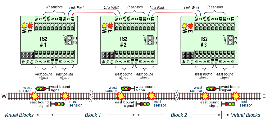
One TS2 circuit operates two LED train signals on a single bi-directional track:
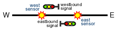
Two block signals at a block boundary, single 2-way track
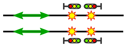
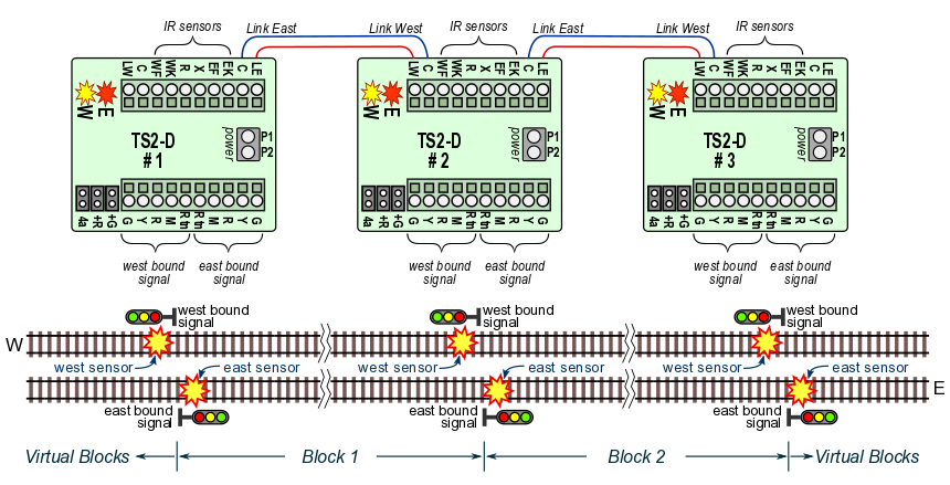
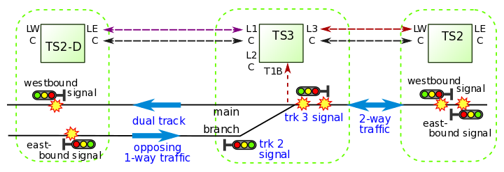
One TS2-D circuit operates two LED train signals on a double-track line:
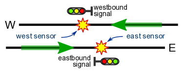
Two block signals at a block boundary, dual one-way tracks
One TS3 circuit operates three trackside signals at the junction of two tracks:
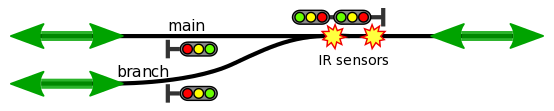
Three trackside signals at a track switch
For double track bi-directional signaling, see the TS5 control point page.
Four block signals at a block boundary, dual bi-directional tracks
Any number of TSx (TS2, TS2-D, TS3, TS5) circuits may be linked to operate a series of cascading block signals:
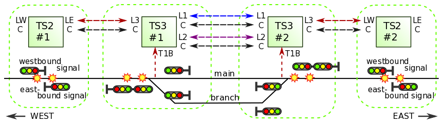
Above -- a passing siding with home and distant signals at both ends uses two TS2 and two TS3 circuits.
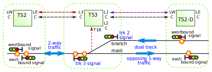
Merging a single 2-way track with two 1-way tracks.
Simple installation
|
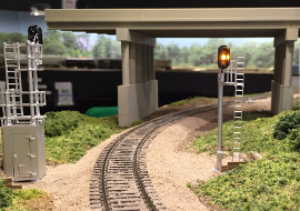 The installation of a TS2 signal system is documented on the Michigan Interstate St. Clair Sub blog site, including photos, video and a detailed narrative. Greg McComas photo |
Designed with modular layouts in mind
- Two adjoining layout modules that each have a TSx signal control circuit can be linked with just two wires per track. The signals on the two modules will then operate together.
- If the next module does not have a TSx circuit then your TSx will automatically sense this and will operate in a timed mode. Signal aspects will change after a train goes by according to a built-in timer.
 |
|
| Supported signal types |
2 LEDs |
 3 LEDs incl. searchlight signals with single tri-color LED |
 B&O color position light with marker |
 PRR |
 Searchlight with bi-color LED (red/green) 2-wire or 3-wire [see note below] |
| 2 aspects • clear • stop |
• green • red |
• green • red |
• green • red |
• vertical • horizontal |
• green • red |
| 3 aspects • clear • approach • stop |
n/a | • green • yellow • red |
• green • yellow • red (marker on or off) |
• vertical • diagonal • horizontal |
• green • yellow • red |
| 4 aspects • clear • advance appr • approach • stop |
n/a | • green • flashing yellow • yellow • red |
• green, marker on • yellow, marker on • yellow, marker off • red, marker on |
n/a |
• green • flashing yellow • yellow • red |
Note: There are two kinds of LED searchlight signals sold for model railroads:
- Bi-color (red/green) - With two or three wires, this is the older type. The red and green portions of the LED are illuminated together to imitate a yellow color. The effectiveness is highly variable depending on the LED itself, ambient lighting and viewing angle. Looking from one side, the 'yellow' signal may appear almost red, and from the other side it may appear very green.
Though the TSx circuits have a jumper setting that allows you to adjust the yellow aspect with more red or more green to compensate, we recommend evaluating one signal first before purchasing signals in quantity.- Tri-color (red/yellow/green) - Newer searchlight signals are available with tri-color LEDs that have a real yellow chip inside the LED, plus the red and green chips. You can easily spot these signals because they have four wires (red, yellow, green and 'common'). They show a real yellow color from all angles and under all lighting conditions. Use tri-color LED searchlight signals for best appearance.
TSx Limitations:
- The TSx detect trains only when they pass by the block boundary.
When linked to another TSx - After a train enters a block, the TSx assumes that block is occupied until a train exits that block. If part of the train uncouples and remains in the block while the rest of the train exits the block, the TSx can only sense that a train exited the block and will then show the block to be clear.
Therefor, where track is not visible to operators, supplemental detection may be used with the TSx circuits to detect stranded rail cars or other obstructions.- While its power is turned off, the TSx cannot sense if trains are added or removed from the track. Therefor, when power is turned on, all signals will initially show an 'approach' aspect to let operators know they should proceed with caution. After the first train passes the infrared sensors, the signals will operate normally.
Interlocking controls:
Forcing a 'stop' condition:
|
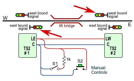 Closing switch S1 will force #1 eastbound signal and #2 westbound signal to show 'stop.' S1 may be linked to a drawbridge, turnout points, a train detector or a dispatcher's switch. Momentarily closing switch S2 will clear the block between TS2 #1 and TS2 #2. |
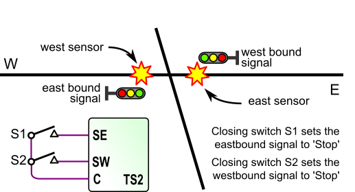
| To create a 'stop' condition at one location, rather than for an entire block as shown above, use a switch or relay to connect terminals 'SE' and 'SW' to a 'C' terminal. In this example, the east/west main line is crossed by a north/south track. Closing switch S1 sets the eastbound signal to 'stop' and closing switch S2 sets the westbound signal to 'stop.' This allows a train to safely cross on the north/south track. The two IR sensors may be placed on opposite sides of the crossing as shown here, or they may both be on the same side. |
 |
Use with a dual head signal:
If the 'M' terminal of the TSx is not used for a B&O marker lamp or for the middle lamp of a PRR signal, the 'M' terminal can be used to light an LED on a second signal head.
|
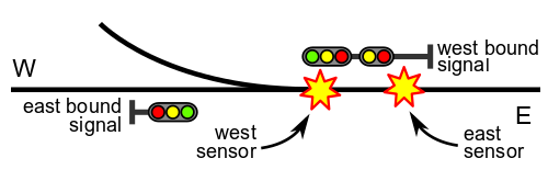 An example of a dual head signal located ahead of a track switch. 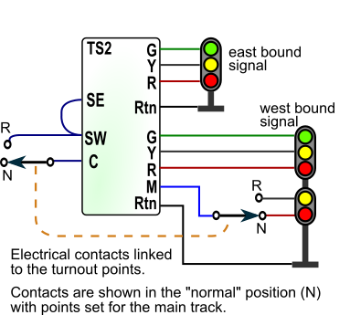 Wiring Details:
|


Looking for more Azatrax Circuits & signals? Click here!


$39.00 US
Country of Origin: United States
Something else you might be interested in: